

 English
 Deutsch
 italiano
 中文简体
中文简体
Author: Admin Date: 2026-04-01
AC Geared Motor: How It Works, Types & Selection Guide
Content
- 1 What Is an AC Geared Motor?
- 2 How an AC Geared Motor Generates Torque and Controls Speed
- 3 Main Types of AC Geared Motors
- 4 Key Technical Specifications Compared
- 5 Single-Phase vs. Three-Phase AC Geared Motors
- 6 Common Industrial Applications
- 7 How to Select the Right AC Geared Motor
- 8 Maintenance Essentials for Long Service Life
What Is an AC Geared Motor?
An AC geared motor is a compact drive unit that combines an alternating current electric motor with an integrated mechanical gearbox into a single, self-contained assembly. The AC motor converts electrical energy from the power supply into rotational mechanical energy, while the gearbox — attached directly to the motor output shaft — reduces the output speed and proportionally increases the output torque. The result is a drive system that delivers precisely controlled rotational speed and high torque in a package that is simpler to install, align, and maintain than a separately sourced motor and gearbox combination.
The integration of motor and gearbox is the key engineering advantage of the geared motor concept. In conventional drive train design, coupling a motor to a gearbox requires careful shaft alignment, coupling selection, and separate mounting arrangements for both components. A geared motor eliminates these challenges by factory-assembling and testing the complete unit before dispatch, ensuring shaft concentricity, correct lubrication, and verified performance across the rated output speed and torque range. This makes AC geared motors one of the most widely deployed drive solutions in industrial automation, material handling, food processing, HVAC systems, and general machinery worldwide.
How an AC Geared Motor Generates Torque and Controls Speed
The operating principle of an AC geared motor begins with the AC induction motor — the most common motor type used in geared motor packages. When alternating current flows through the stator windings, it creates a rotating magnetic field. This rotating field induces currents in the rotor conductors, which in turn generate their own magnetic field that interacts with the stator field to produce rotational force — torque — on the rotor shaft. The speed at which the stator field rotates is called the synchronous speed and is determined by the supply frequency and the number of motor pole pairs. At 50 Hz with a four-pole motor, synchronous speed is 1,500 rpm; at 60 Hz, it is 1,800 rpm. The actual rotor speed is slightly lower than synchronous speed due to slip — typically 3 to 5 percent — giving full-load speeds of approximately 1,450 rpm at 50 Hz or 1,720 rpm at 60 Hz.
These base motor speeds are far too high for most direct-drive applications. The gearbox stages this speed down through a fixed gear ratio — for example, a 50:1 ratio reduces 1,450 rpm to 29 rpm at the output shaft — while multiplying the available torque by approximately the same factor, less transmission efficiency losses. Gear ratios in commercial AC geared motors typically range from 3:1 to 1,500:1, allowing output speeds from a few hundred rpm down to less than one rpm for very slow, high-torque applications. The gear ratio is selected at the design stage based on the application's required output speed and torque, and it is a fixed mechanical parameter of the unit — unlike variable speed drives, which control speed electronically.
Main Types of AC Geared Motors
AC geared motors are available in several configurations defined by the type of gearing mechanism used in the gearbox stage. Each gearing type has distinct characteristics in terms of gear ratio range, efficiency, noise level, load capacity, and physical footprint. Selecting the correct type for a given application is as important as specifying the correct power rating.
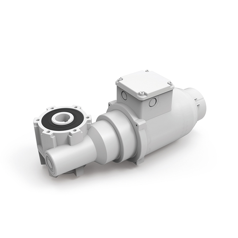
Helical Geared Motors
Helical gear sets use teeth cut at an angle to the gear axis, allowing multiple teeth to engage simultaneously as the gears rotate. This progressive tooth engagement produces smooth, quiet operation and high load-carrying capacity compared to straight-cut spur gears of equivalent size. Helical geared motors achieve efficiencies of 94 to 98 percent per gear stage, making them the most energy-efficient geared motor type in common use. They are the default choice for conveyor systems, mixers, packaging machinery, and any application where smooth operation and energy efficiency are priorities. Inline helical geared motors — where the input and output shafts share the same axis — are particularly compact and well-suited to space-constrained installations.
Bevel-Helical Geared Motors
Bevel-helical geared motors incorporate a bevel gear stage at the motor input that redirects the drive at 90 degrees, allowing the output shaft to be perpendicular to the motor shaft. This right-angle configuration is essential when the available installation space or the driven machine geometry requires the motor to be mounted parallel to, rather than in line with, the load. Despite the directional change, bevel-helical units maintain high efficiency — typically 92 to 96 percent — because the helical cutting of the bevel teeth reduces noise and improves load distribution compared to straight bevel gears. They are widely used in agitators, screw conveyors, and cooling tower fans.
Worm Geared Motors
Worm geared motors use a worm screw meshing with a worm wheel to achieve high gear ratios — typically 5:1 to 100:1 — in a single compact stage. The right-angle shaft arrangement is inherent to the worm gear design. The primary advantages of worm geared motors are their compact size relative to gear ratio, their ability to achieve high ratios in a single stage, and their inherent self-locking property at high ratios, which prevents the load from back-driving the motor when power is removed. This self-locking behavior is valuable in gate actuators, lifting mechanisms, and positioning systems where the load must hold position without a brake. The trade-off is lower efficiency — typically 50 to 85 percent depending on ratio and lubrication — and higher heat generation, which requires careful thermal management in high-duty-cycle applications.
Planetary Geared Motors
Planetary geared motors use a gear arrangement in which multiple planet gears orbit around a central sun gear while meshing with an outer ring gear. This configuration distributes the transmitted load across several gear meshes simultaneously, allowing a planetary gearbox to transmit very high torque relative to its physical size. Planetary geared motors are more compact and more torsionally stiff than equivalent helical or worm units, making them the preferred choice in robotics, precision positioning stages, automated guided vehicles, and servo drive systems where high torque density and minimal backlash are critical requirements. Efficiencies typically range from 90 to 97 percent depending on the number of stages.
Key Technical Specifications Compared
The following table summarizes the most important performance characteristics of the four main AC geared motor types to assist in preliminary selection.
| Type | Efficiency | Ratio Range | Output Shaft | Best For |
| Helical | 94–98% | 3:1 – 500:1 | Inline or parallel | Conveyors, mixers, packaging |
| Bevel-Helical | 92–96% | 5:1 – 400:1 | Right angle (90°) | Agitators, screw conveyors, fans |
| Worm | 50–85% | 5:1 – 100:1 | Right angle (90°) | Gates, lifts, positioning |
| Planetary | 90–97% | 3:1 – 1,000:1 | Inline (coaxial) | Robotics, AGVs, servo systems |
Single-Phase vs. Three-Phase AC Geared Motors
AC geared motors are available for both single-phase and three-phase power supplies, and the choice between them has significant implications for performance, starting characteristics, and installation requirements.
Single-Phase AC Geared Motors
Single-phase motors operate from standard domestic or light commercial power supplies — typically 110V or 230V at 50 or 60 Hz. They are suitable for lower power applications, generally up to 2.2 kW, and are commonly used in light-duty machinery, household appliances, gate operators, and small conveyor systems. Single-phase induction motors require a capacitor or auxiliary winding to generate the phase shift needed for starting, which adds a component that may need periodic replacement. Starting torque is lower than equivalent three-phase motors, and efficiency is somewhat reduced at higher load levels.
Three-Phase AC Geared Motors
Three-phase motors are the industrial standard for power ratings from 0.18 kW upward and are used in the vast majority of production and process equipment worldwide. They are inherently self-starting — no capacitor is required — and deliver smoother, more balanced torque output across the full speed range. Three-phase geared motors are more energy-efficient than single-phase equivalents, produce less heat per unit of output power, and are mechanically simpler and more reliable due to the absence of starting capacitors and auxiliary windings. For any industrial application where three-phase supply is available, three-phase AC geared motors are the strongly preferred choice.
Common Industrial Applications
AC geared motors serve an exceptionally broad range of applications across virtually every manufacturing and process industry. Their reliability, cost-effectiveness, and availability in an almost unlimited range of power ratings, gear ratios, and mounting configurations make them the default drive solution for countless machine functions.
- Conveyor and material handling systems: Belt conveyors, roller conveyors, and chain conveyors rely on AC geared motors to drive the moving surface at controlled, consistent speeds. Helical inline and bevel-helical geared motors are most commonly used in this sector due to their high efficiency and smooth torque delivery.
- Mixing and agitation equipment: Industrial mixers for food, chemical, pharmaceutical, and paint production use AC geared motors to drive impellers and agitators at low speeds with high torque. The continuous duty cycle in mixing applications requires motors with good thermal ratings and robust gearbox sealing against process contamination.
- Packaging machinery: Filling machines, labeling systems, capping equipment, and carton erectors use AC geared motors — often paired with variable frequency drives — to synchronize multiple axes and adjust line speed during production changeovers.
- HVAC and cooling systems: Cooling tower fans, air handling unit drives, and pump systems in heating and ventilation installations use AC geared motors for their reliability and low maintenance requirements in continuous 24/7 operation environments.
- Gate, door, and barrier actuators: Worm geared motors are the dominant choice for automatic gates, rolling shutters, and vehicle barriers, where the self-locking property of the worm gear holds the gate in position without power and provides a safety margin against unauthorized manual operation.
- Food and beverage processing: Wash-down rated AC geared motors with stainless steel housings and sealed gearboxes are used extensively in food production environments where regular high-pressure cleaning with detergents is required and contamination of the product must be absolutely prevented.
How to Select the Right AC Geared Motor
Correct AC geared motor selection requires working through a defined set of application parameters systematically. Undersizing a geared motor leads to overheating, premature failure, and unplanned downtime; oversizing increases purchase cost, energy consumption, and physical footprint unnecessarily. The following parameters should be established before specifying a unit.
- Required output speed: Determine the shaft speed needed at the driven load in rpm. This, combined with the motor's base speed, defines the required gear ratio. Account for any speed adjustment planned through a variable frequency drive, which may allow a higher gear ratio unit to cover a range of speeds.
- Required output torque: Calculate the torque needed to accelerate and run the load, including any peak demand during starting or load surges. Select a geared motor whose rated output torque exceeds this figure with an appropriate service factor — typically 1.25 to 2.0 depending on the duty cycle and shock load severity.
- Duty cycle and thermal rating: Continuous duty (S1) applications require a motor rated for full load without thermal derating. Intermittent or cyclic duty applications may allow a smaller motor to be used if the off-time is sufficient for the motor to cool between load cycles.
- Mounting configuration: Determine whether the application requires a foot-mounted, flange-mounted, or shaft-mounted geared motor, and whether the output shaft orientation must be inline, parallel, or at right angles to the motor axis. Confirm available space envelope dimensions before finalizing the selection.
- Environmental requirements: Specify the ingress protection (IP) rating required for the installation environment. Standard industrial locations typically require IP55 (dust-tight and jet-water resistant). Outdoor, washdown, or submersible applications require IP65, IP66, or IP67 ratings. Food industry applications may additionally require FDA-compliant gearbox lubricants and stainless steel or coated aluminum housings.
- Power supply compatibility: Confirm the available supply voltage and frequency and specify the motor winding accordingly. For applications using a variable frequency drive, confirm the motor is inverter-rated to withstand the voltage spikes associated with PWM drive output waveforms without insulation damage.
Maintenance Essentials for Long Service Life
AC geared motors are among the most robust and low-maintenance drive components available, but a modest preventive maintenance program significantly extends service life and reduces the risk of unplanned failures. The gearbox and motor each have specific maintenance needs that should be addressed on a defined schedule.
- Check gearbox oil level and condition at the manufacturer-specified intervals — typically every 5,000 operating hours or annually, whichever comes first. Darkened, milky, or metallic-particle-contaminated oil indicates wear or seal failure and should prompt immediate investigation and oil change.
- Inspect shaft seals and housing gaskets for oil leakage at each routine inspection. Even minor oil loss reduces lubrication film thickness on gear teeth and bearings, accelerating wear and shortening the interval to the next major failure.
- Monitor motor operating temperature using a contact thermometer or thermal imaging camera. A motor running consistently above its rated temperature class limit — Class F is 155°C maximum winding temperature — is operating under thermal stress that shortens winding insulation life significantly.
- Check output shaft coupling or sprocket for wear, looseness, and misalignment at each maintenance interval. Misalignment between the geared motor output shaft and the driven shaft generates radial loads on the output bearing that exceed its design rating, leading to premature bearing failure.
- Keep ventilation openings and cooling fins clean and unobstructed. In dusty or fibrous environments, accumulated debris on motor cooling fins can reduce heat dissipation sufficiently to raise winding temperature by 10°C to 20°C above design levels, with a corresponding reduction in insulation life.

-
Feedback
Related products

Hotline:0086-15869193920
Time:0:00 - 24:00
