

 English
 Deutsch
 italiano
 中文简体
中文简体
Author: Admin Date: 2026-03-23
How to Test a DC Motor: Step-by-Step Guide with a Multimeter
Content
- 1 How to Test a DC Motor: The Complete Diagnostic Approach
- 2 Safety Precautions Before You Begin
- 3 Step 1 — Visual Inspection: What to Look for Before Measuring
- 4 Step 2 — Winding Resistance Test with a Multimeter
- 5 Step 3 — Insulation Resistance Test (Megger Test)
- 6 Step 4 — No-Load Run Test: Checking Current, Speed, and Behavior
- 7 Step 5 — Back-EMF Test: Verifying Armature Integrity
- 8 Step 6 — Loaded Current Draw Test
- 9 DC Motor Fault Diagnosis Reference Table
- 10 Testing BLDC Motors: Additional Considerations
- 11 When to Repair vs. Replace a DC Motor
How to Test a DC Motor: The Complete Diagnostic Approach
Testing a DC motor correctly means more than applying voltage and checking whether the shaft spins. A motor that runs erratically, draws excessive current, overheats, produces abnormal noise, or fails intermittently requires a structured diagnostic process to identify the root cause — whether that is a shorted winding, worn brushes, failing bearings, contaminated commutator, or insulation breakdown.
The good news is that most DC motor faults can be identified with basic test equipment: a digital multimeter (DMM), a clamp meter, and in some cases a megohmmeter (insulation resistance tester). A systematic test sequence — performed before and during motor operation — will accurately diagnose the vast majority of DC motor failures without requiring specialized laboratory equipment. This guide covers that sequence in full, from pre-power-up bench tests through loaded operational checks.
Safety Precautions Before You Begin
DC motor testing involves both electrical and mechanical hazards. Before starting any test procedure, observe the following safety requirements without exception:
- Disconnect and lock out power — Isolate the motor from its power supply and apply lockout/tagout (LOTO) before performing any off-power tests. Confirm zero energy state with a voltage tester before touching terminals.
- Discharge capacitors — If the motor circuit includes capacitors (common in drive systems), allow adequate discharge time or use a bleed resistor before contact.
- Secure the shaft — When performing bench tests on a disconnected motor, secure the shaft or be aware that applying voltage for rotation testing will cause the shaft to spin — a mechanical hazard.
- Use rated test equipment — Ensure your multimeter and insulation tester are rated for the voltages involved. Standard DMMs are rated for CAT III or CAT IV environments; use the correct category for your test location.
- Wear PPE — Safety glasses and insulating gloves are required when working on live circuits or performing rotation tests.
Step 1 — Visual Inspection: What to Look for Before Measuring
A careful visual inspection takes less than five minutes and frequently identifies the fault before any instrument is picked up. Skipping this step wastes time and can miss obvious damage that instrument testing alone will not reveal.
Exterior and Housing
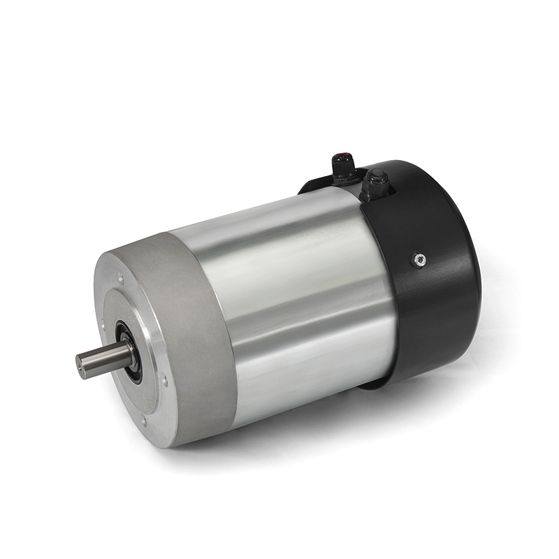
Inspect the motor housing for cracks, burn marks, discoloration from overheating, and physical damage. Brown or black discoloration around ventilation slots indicates sustained overheating — often caused by overloading, blocked ventilation, or shorted windings. Check that all mounting hardware is intact and the motor is properly aligned with its driven load.
Terminal Block and Wiring
Examine the terminal block for corrosion, loose connections, burn marks, and damaged insulation on lead wires. Loose terminals cause resistance heating that mimics winding faults in electrical tests. Melted insulation or burn marks at the terminal block point to overload or short-circuit events in the motor's operating history.
Brush Access and Commutator (Brushed DC Motors)
On brushed DC motors, remove the brush access covers and inspect brush length, spring tension, and commutator surface condition. Brushes worn to less than one-third of their original length require immediate replacement. The commutator surface should be smooth, uniformly copper-colored, and free of scoring, pitting, or excessive carbon deposits. A dark, evenly distributed film on the commutator is normal and beneficial (called "patina" or "glaze"); uneven deposits, bright spots, or groove patterns indicate problems.
Shaft and Bearings
Rotate the shaft by hand. It should turn smoothly with consistent, light resistance. Roughness, grinding, or hard spots indicate bearing damage and require replacement before the motor is returned to service — failed bearings cause abnormal current draw, vibration, and will eventually destroy the armature. Check for axial (end-to-end) play in the shaft; more than 0.5 mm of free movement in a typical motor indicates bearing wear.
Step 2 — Winding Resistance Test with a Multimeter
The winding resistance test is the most fundamental electrical test for a DC motor. It detects open circuits (broken windings), short circuits between windings, and — in conjunction with the motor's nameplate data — identifies gross insulation failures within the winding itself.
Equipment Required
Digital multimeter set to the resistance (Ω) function. For very low resistance values (below 1 Ω, common in high-current armature windings), a four-wire (Kelvin) resistance meter or a dedicated low-resistance ohmmeter provides more accurate readings by eliminating test lead resistance from the measurement.
Procedure for Brushed DC Motors
- With power fully disconnected, set the DMM to the lowest resistance range that covers the expected value.
- Zero the meter (short the test leads and note any offset; subtract this from all readings).
- Armature winding: Place one probe on each brush (or each armature terminal). Slowly rotate the shaft by hand while observing the resistance reading. The reading should vary smoothly — typically between 0.5 Ω and 10 Ω for small to medium motors — cycling through values as different commutator segments come into contact with the brushes. Sudden open circuit (OL / infinite resistance) indicates a broken armature winding. A reading of near zero (0 Ω) at any position indicates a short circuit between commutator segments.
- Field winding (series or shunt wound motors): Measure between the field terminals. The resistance should be stable and match the nameplate or manufacturer specification. An open reading indicates a broken field coil; a significantly lower than expected reading suggests a shorted turn within the field winding.
Procedure for Brushless DC (BLDC) Motors
BLDC motors have three-phase stator windings (labeled U, V, W or A, B, C). Measure resistance between each pair of terminals: U-V, V-W, and U-W. All three readings should be equal — typically within ±5% of each other, and matching the manufacturer's specification. An open circuit (OL) in any phase indicates a broken winding. Unequal readings suggest a partial short or connection fault in one phase. A reading of zero in any phase indicates a direct short circuit.
Step 3 — Insulation Resistance Test (Megger Test)
The insulation resistance test — commonly called a "Megger test" after the instrument used — measures the resistance between the motor windings and the motor frame (ground). It detects insulation degradation caused by moisture ingress, contamination, mechanical damage, and thermal aging before a full insulation breakdown (ground fault) occurs.
A standard DMM cannot perform this test reliably. An insulation resistance tester (megohmmeter) applies a DC test voltage — typically 500V DC for motors rated up to 1,000V — and measures the resulting leakage current to calculate insulation resistance in megohms (MΩ).
Procedure
- Disconnect the motor from all power sources and from its controller or drive. Short all motor terminals together to form one test point.
- Connect one megohmmeter lead to the shorted motor terminals and the other to the motor frame (earth/ground).
- Apply the test voltage for 60 seconds and record the insulation resistance reading.
- For a more detailed assessment, record readings at 1 minute and 10 minutes. The ratio (10-minute reading ÷ 1-minute reading) is called the Polarization Index (PI). A PI above 2.0 indicates good insulation; below 1.0 indicates seriously degraded insulation.
Interpreting Results
The general industry guideline per IEEE 43 is that insulation resistance should be at minimum 1 MΩ per 1,000V of rated voltage, plus 1 MΩ. For a 24V DC motor, a minimum of approximately 1 MΩ is acceptable; for a 500V DC motor, the minimum is 1.5 MΩ. In practice, a healthy motor should read well above 100 MΩ. Readings below 1 MΩ indicate immediate risk of ground fault; readings between 1–10 MΩ indicate insulation degradation requiring monitoring or remediation.
Step 4 — No-Load Run Test: Checking Current, Speed, and Behavior
After passing the bench electrical tests, the motor is ready for a controlled power-up test under no-load conditions. This test reveals mechanical faults, commutation problems, and gross electrical imbalances that static resistance tests cannot detect.
Equipment Required
A regulated DC power supply (or the motor's rated power source), a clamp meter or series ammeter to measure current, and optionally a tachometer to verify shaft speed.
Procedure
- Apply rated voltage to the motor terminals with no mechanical load on the shaft. Use a current-limited power supply if available to protect against startup surges.
- Observe startup behavior. The motor should accelerate smoothly to speed. Hesitation, stuttering, or failure to start from certain shaft positions in a brushed motor indicates commutator or brush problems.
- Measure no-load current with the clamp meter once the motor reaches steady speed. Compare to the motor's nameplate no-load current specification. No-load current significantly above specification indicates bearing friction, shorted turns, or incorrect supply voltage.
- Measure shaft speed with a tachometer and compare to nameplate rated speed (corrected for no-load conditions — actual no-load speed will be slightly above rated load speed for brushed motors).
- Listen for abnormal sounds: grinding (bearing damage), intermittent sparking sounds (commutation problems), high-pitched whining (resonance or imbalance), or rhythmic thumping (mechanical imbalance or eccentric rotor).
- Run for 5–10 minutes and check motor temperature by touch or infrared thermometer. Excessive temperature under no-load conditions indicates shorted windings, bearing problems, or inadequate ventilation.
Step 5 — Back-EMF Test: Verifying Armature Integrity
The back-EMF (electromotive force) test measures the voltage generated by the motor when driven as a generator — confirming that the armature winding and magnetic field are producing the expected output. It is a particularly useful diagnostic for detecting shorted armature turns that resistance testing may miss.
Procedure
- Disconnect the motor from its power supply entirely.
- Connect a multimeter set to DC voltage across the motor's armature terminals.
- Spin the motor shaft manually at a consistent speed (or use a drill or second motor coupled to the shaft for more controlled results).
- Observe the voltage reading. A healthy permanent magnet DC motor should generate a measurable DC voltage proportional to shaft speed — typically in the range of several volts per 1,000 RPM depending on motor design.
A very low or zero back-EMF reading when the shaft is spinning confirms a problem with the armature winding or, in a wound-field motor, with the field winding. A weak but non-zero reading may indicate shorted armature turns reducing the effective turns count in the winding.
Step 6 — Loaded Current Draw Test
The definitive operational test connects the motor to its actual load or a controlled test load and measures current draw at rated operating conditions. This test validates the motor's overall health under the conditions it will actually experience in service.
What to Measure
- Full-load current — Should not exceed the nameplate rated current by more than 5–10% under rated load conditions. Consistently elevated current indicates the load is too heavy, the supply voltage is below specification, or the motor has an internal fault increasing its losses.
- Startup (inrush) current — DC motors draw significantly higher current at startup than during steady-state running — typically 6–10 times the full-load current for direct-across-the-line starts. Abnormally low inrush current may indicate high-resistance connections; abnormally high sustained current after startup indicates mechanical binding or electrical faults.
- Current ripple or fluctuation — Smooth, stable current draw indicates a healthy motor. Periodic current fluctuations synchronized with shaft rotation in a brushed motor point to commutator segment problems or uneven winding resistance.
DC Motor Fault Diagnosis Reference Table
The following table maps common DC motor symptoms to their most likely causes and the test method that confirms or rules out each fault:
| Symptom | Most Likely Cause | Confirming Test |
|---|---|---|
| Motor does not start at all | Open circuit winding, broken brush, no supply voltage | Resistance test (OL reading), voltage check at terminals |
| Runs but draws excessive current | Shorted winding, bearing failure, overloaded | Resistance test (low reading), shaft rotation check, load audit |
| Runs slower than rated speed | Low supply voltage, overload, worn brushes, shorted turns | Voltage measurement at terminals, no-load speed test, back-EMF test |
| Overheating under normal load | Shorted winding turns, blocked ventilation, bearing friction | Winding resistance test, visual inspection of vents, shaft rotation test |
| Intermittent operation or stalling | Worn brushes, dirty commutator, loose connection | Brush inspection, commutator cleaning/test, terminal tightness check |
| Excessive sparking at brushes | Wrong brush grade, commutator damage, shorted commutator segments | Visual inspection, resistance between adjacent commutator segments |
| Trips ground fault protection | Insulation breakdown (winding to ground) | Megger test (insulation resistance <1 MΩ) |
| Grinding or rough rotation | Bearing damage or contamination | Manual shaft rotation, vibration analysis, bearing inspection |
Testing BLDC Motors: Additional Considerations
Brushless DC motors share the winding resistance and insulation tests described above but require additional checks specific to their electronic commutation system.
Hall Effect Sensor Testing
Most BLDC motors use three Hall effect sensors to detect rotor position and signal the motor controller when to switch current between phases. To test Hall sensors: apply 5V DC to the sensor supply pin (Vcc) and ground, then slowly rotate the motor shaft while monitoring the output pin of each sensor with a multimeter in DC voltage mode. Each sensor should switch cleanly between approximately 0V (low) and 5V (high) as the rotor magnet passes. A sensor that stays permanently high, permanently low, or outputs an intermediate voltage is faulty and must be replaced.
Phase-to-Phase Inductance Balance
For a more detailed assessment of BLDC stator winding condition, an LCR meter can measure inductance between each phase pair (U-V, V-W, U-W). As with resistance, all three readings should be approximately equal — typically within ±5% of each other. Significant inductance imbalance between phases indicates a partial short circuit or damaged winding in one phase.
Back-EMF Waveform Check
When a BLDC motor is spun externally, each phase generates a back-EMF waveform. Using an oscilloscope to monitor all three phases simultaneously while spinning the shaft reveals winding faults clearly: the three waveforms should be identical in amplitude and separated by 120° in time. A reduced-amplitude waveform on one phase confirms shorted turns in that phase. This test is particularly useful for high-value BLDC motors where precise fault localization is needed before committing to repair or replacement.
When to Repair vs. Replace a DC Motor
After completing the test sequence, the decision to repair or replace depends on the fault identified, the motor's size and value, and the availability of spare parts.
- Replace brushes and clean the commutator — Always cost-effective for brushed DC motors. This repair resolves the majority of intermittent operation, sparking, and performance degradation issues in brushed motors and is within the capability of a competent technician.
- Replace bearings — Cost-effective for medium and large motors. Bearing replacement restores smooth operation and prevents secondary damage to windings from vibration. For fractional-horsepower motors, the total repair cost may approach the replacement cost — evaluate case by case.
- Rewind armature or stator — Economically justified only for large, high-value motors (typically above 5 kW). Rewinding a small DC motor costs more than purchasing a replacement in most markets. For industrial motors, rewinding by a specialist motor shop is standard practice.
- Replace the motor — The correct decision for small fractional-horsepower motors with shorted windings or severe insulation breakdown, and for any motor where the cumulative repair cost exceeds 50% of replacement cost. Document the failure mode to inform motor selection for the replacement — if the failure was due to systematic overloading or an unsuitable IP rating for the environment, the same fault will recur in a direct replacement without addressing the root cause.

-
Feedback
Related products

Hotline:0086-15869193920
Time:0:00 - 24:00
